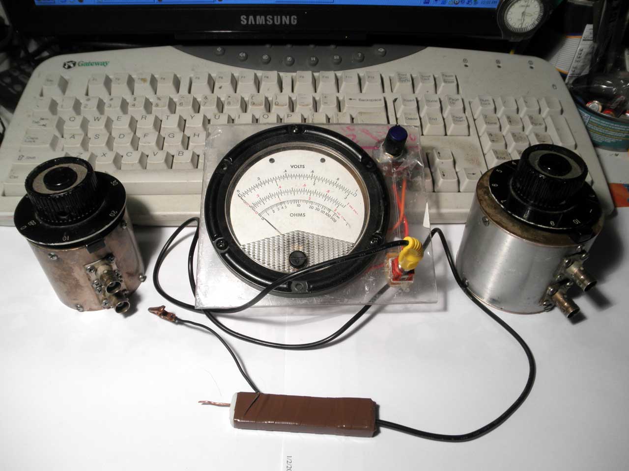
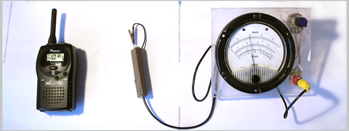
RF detector or probe, along with two attenuators in the picture below. It's hard to explain how this combination becomes a powerful tool for high-frequency measurements, and I will not do that.
Let's focus on a high-frequency probe. It was designed for frequency range 10 - 200 MHz. It is very simple, as you can see on the right picture.
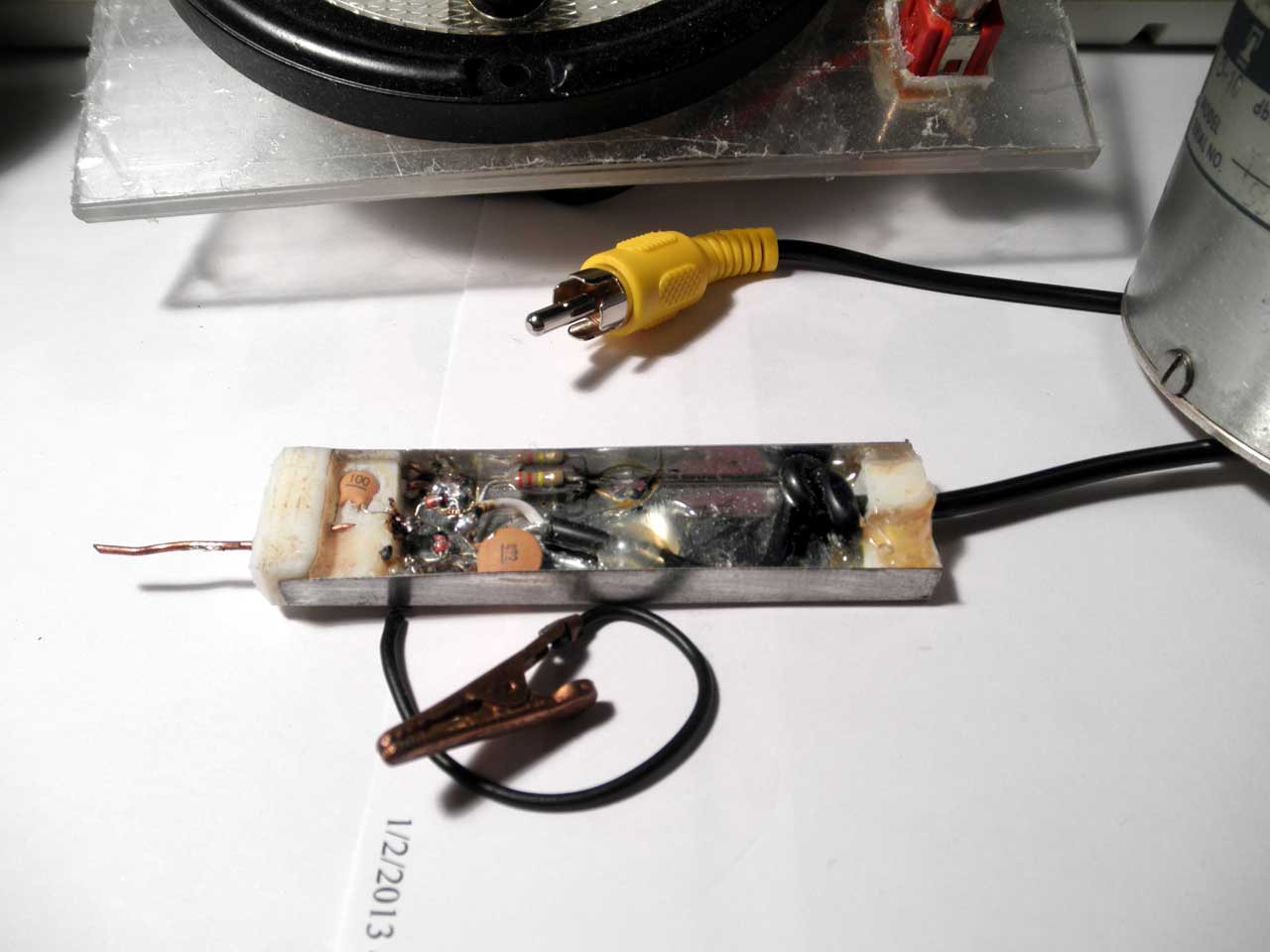
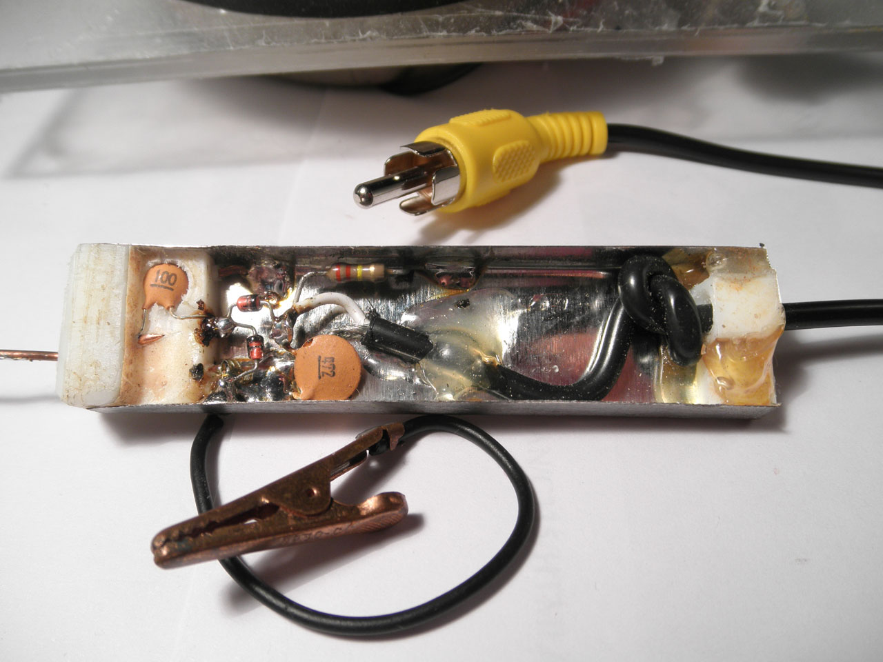
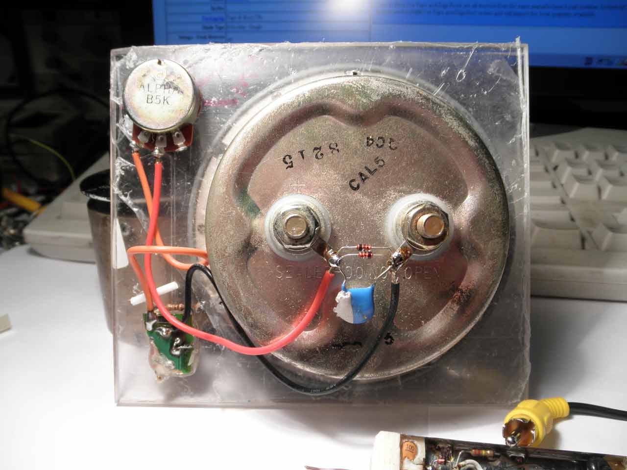
No one has a time to investigate what is in the middle, so the schematic diagram below.

Diodes D1, D2 - RF Mixer or Detector Diodes. From them will depend the top frequency at which the detector will work. High-speed switching diodes (as 1N4148, or even fastest), after 70 MHz - useless. D3, D4 - any. They only limit the voltage on the micro-ammeter head, below 0.8 Volts (just in case). C1, C2 must be RF ceramic. The rest - do not affect to the quality. Just hold connections between elements (inside RF probe) as short as possible. In this design, which you can see below (see a distance between elements), the maximum frequency will be limited up to 1 GHz, even with 'the best of the best' Detector Diodes ...
Remember that the reverse voltage (Vr), for most of Mixer and Detector Diodes, does not exceed 5 Volts. After that, they start to drain current. This means that the detector's output voltage must not exceed Vr (max).
Remember that the reverse voltage (Vr), for most of Mixer and Detector Diodes, does not exceed 5 Volts. After that, they start to drain current. This means that the detector's output voltage must not exceed Vr (max).
I use this RF detector to check and adjust antennas / transmitters at 135 - 136 MHz. But it's part of my job and it's not interesting. For fun, we can see what type of modulation used in radio-controlled toys. To do this, arrange the detector close to the antenna, and connect oscilloscope probe to the junction of resistors R2 and R3. As result, we can see 100% AM modulation.
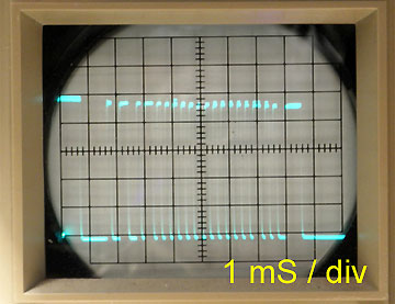
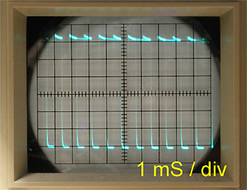
On the pictures. Remote control transmitter 27 MHz on the left, and 49 MHz on the right. Offset for both ' -3 div, DC'.
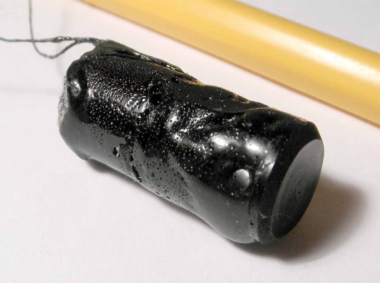
On the next photo is something and that is very hard to say what it is. I can only say that it has made complex fault (made 'random noise') for our equipment. In any case, at 145 MHz & 100% AM, it sends a serial data 3 sec long, every 15 min.
On the next photo is something and that is very hard to say what it is. I can only say that it has made complex fault (made 'random noise') for our equipment. In any case, at 145 MHz & 100% AM, it sends a serial data 3 sec long, every 15 min.
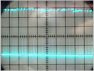
It's hard to catch with a conventional oscilloscope, since the package is very long. But, thank God, that we have free programs that turn a laptop into a digital oscilloscope with memory. Next image has been captured by a program called 'Virtual Analyzer'. The same point (between resistor R2 & R3) was connected to computer's Audio Input (not a 'Mic' Input).
It's hard to say to what is a maximum frequency for this design. At 430 MHz it working fine, but not as good as I would like.
And the last. This detector has a limited input voltage (limited by Vr (max) applied diodes), and this makes it easy to burn one or both diodes. The attenuator is a good idea to limit input voltage, but no one has it. For RF voltages over 3 Volts, the most simple solution is to solder an additional capacitor 0.5 - 5 pF to the detector's input. It works well.
*** Attenuators, which you can see on the first picture work ONLY with a 50 Ohms load. I use a 50 Ohms terminator with pre-drilled side hole in order to get access to the center pin.
*** Attenuators, which you can see on the first picture work ONLY with a 50 Ohms load. I use a 50 Ohms terminator with pre-drilled side hole in order to get access to the center pin.
Additional information.
"Schottky diodes selection guide"
from www.rfmicrowave.it (saved .pdf).
"RF Schottky Diodes for High Frequency Detector Mixer or Power Leveling"
from www.infineon.com
"High Performance Schottky Diodes"
from www.skyworksinc.com
"Schottky diodes selection guide"
from www.rfmicrowave.it (saved .pdf).
"RF Schottky Diodes for High Frequency Detector Mixer or Power Leveling"
from www.infineon.com
"High Performance Schottky Diodes"
from www.skyworksinc.com